Cryogenic Motion / Cryogenic Goniometer
Cryogenic Goniometer
Long Stroke,Heavy Duty Tilting
Fixed-Center Tilting: Higher Load, Superior Reliability
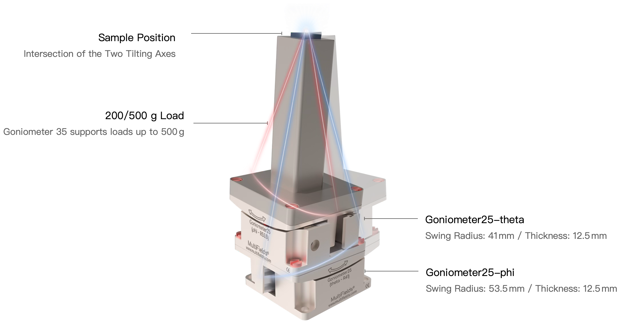
1The Goniometer Series tilt stages can support higher loads and offer enhanced reliability. When theta and phi models are used together, the sample can be positioned at a fixed point for X/Y dual-axis rotation.
2No special drive cables are needed. All parameters here are measured with 50 Ω cables.
Specifications
Explore Your Options
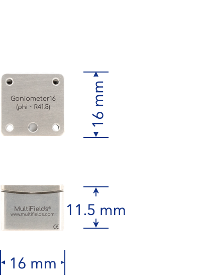
Goniometer16
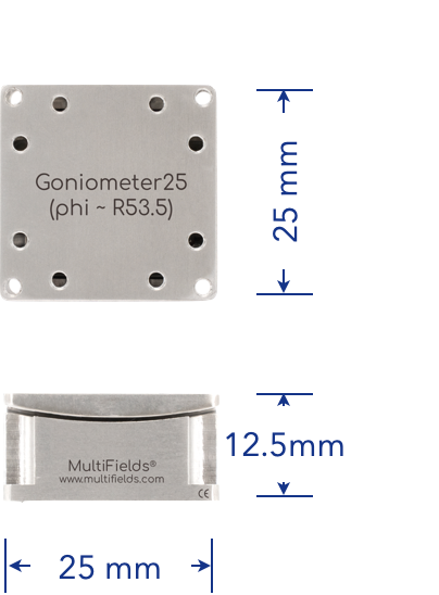
Goniometer25
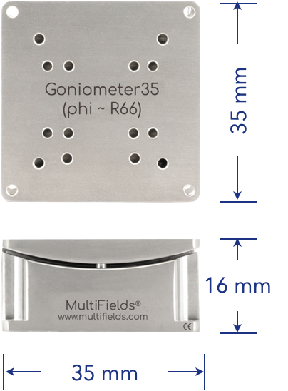
Goniometer35
➨ Version
Standard Version
2 × 10⁻⁷ mbar
1.4 K ~ 350 K
✔
✔
✔
.UHV, Ultra-High Vacuum Version
2 × 10-11 mbar
1.4 K ~ 350 K
✔
✔
✔
.ULT, Cryogenic Version
2 × 10⁻⁷ mbar
10 mK ~ 350 K
✔
✔
✔
.UHV.ULT, Ultra-High Vacuum & Cryogenic Version
2 × 10-11 mbar
10 mK ~ 350 K
✔
✔
✔
➨ Mechanical Specifications
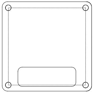
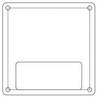
1 Dimensions
Zero Position
16 × 16 × 11.5
( mm × mm × mm )
25 × 25 × 12.5
( mm × mm × mm )
35 × 35 × 16
( mm × mm × mm )
2 Materials
Standard Version
.UHV
.ULT
.UHV.ULT
Titanium Alloy; 10 g
Titanium Alloy; 10 g
Beryllium Copper; 17 g
Beryllium Copper; 17 g
Titanium Alloy; 20 g
Titanium Alloy; 20 g
Beryllium Copper; 34 g
Beryllium Copper; 34 g
Titanium Alloy; 70 g
Titanium Alloy; 70 g
Beryllium Copper; 114 g
Beryllium Copper; 114 g
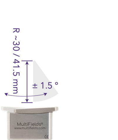
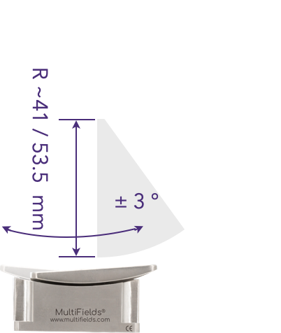
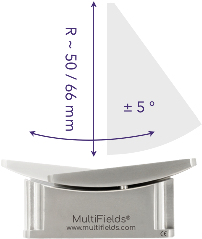
3 Travel Range
3 °
6 °
10 °
4 Swing Radius
(Distance from Rotation Center to Working Surface)
Goniometer16-phi:
41.5 mm
Goniometer16-theta:
30 mm
Goniometer25-phi:
53.5 mm
Goniometer25-theta:
41 mm
Goniometer35-phi:
66 mm
Goniometer35-theta:
50 mm
➨ Motion and Positioning
5 Maximum Speed
@ 300 K
~ 1 °/s
~ 1 °/s
~ 1 °/s
6 Maximum Load
50 g
200 g
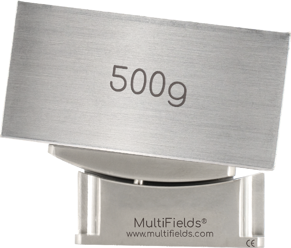
500 g
7 Driving Force
1.5 N
2 N
3 N
8 Minimum Incremental Motion
50 μ°
50 μ°
50 μ°
9 Fine Adjustment Resolution
@ 2 K
0.5 μ°
0.5 μ°
0.5 μ°
10 Sensor
Type
Measurement Range
Resolution
Power Consumption
Resistive Position Sensor
3 °
6 °
10 °
0.2 m°
0.2 m°
0.5 m°
1 mW (1 μW optional for cryogenic applications)
➨ Installation & Operation
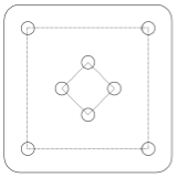
11 Mounting Options
Goniometer16
Surface·Threaded Hole
4 pcs – M1.6 × 2 mm
11.5 mm × 11.5 mm
4 pcs – M1.6 × 2 mm
Φ 5.0 mm
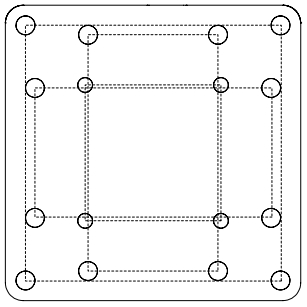
Goniometer25
Surface·Threaded Hole
4 pcs – M1.6 × 2 mm
11.5 mm × 11.5 mm
4 pcs – M2 × 2 mm
21.6 mm × 21.6 mm
4 pcs – M2 × 2 mm
11 mm × 20 mm
4 pcs – M2 × 2 mm
20 mm × 11 mm
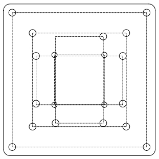
Goniometer35
Surface·Threaded Hole
4 pcs – M1.6 × 2 mm
11.5 mm × 11.5 mm
4 pcs – M2 × 2 mm
21.6 mm × 21.6 mm
3 pcs – M2 × 2 mm
11 mm × 20 mm
3 pcs – M2 × 2 mm
20 mm × 11 mm
4 pcs – M2 × 2 mm
31 mm × 31 mm
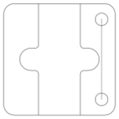
Goniometer16
Base·Mounting Hole
2 pcs – Φ 2.1 mm
11.5 mm – 2
Goniometer25
Base·Mounting Hole
4 pcs – Φ 2.1 mm
21.6 mm × 21.6 mm
Goniometer35
Base·Mounting Hole
4 pcs – Φ 2.1 mm
31 mm × 31 mm
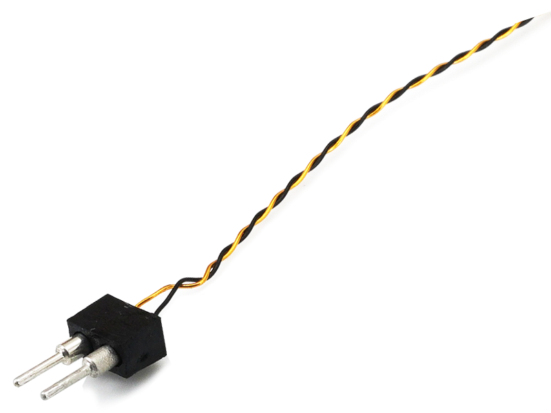
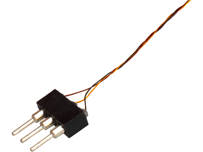
12 Cable & Connector
Actuator Cables & Connectors
Sensor Cables & Connectors
Twisted Phosphor Bronze Wires
2 mm Header Pin (1 × 2 Pin)
Phosphor Bronze Twisted Trio
2 mm Header Pin(1 × 3 pin)
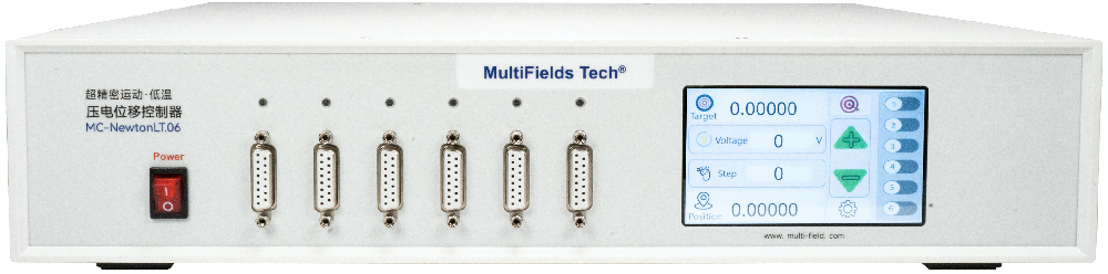
13 Controller
MC-NewtonLT.06
Product Information
Download List
Product Declarations
2D / 3D Files
Manuals
Goniometer 系列产品手册
Consultation Purchase
Contact us